Achieving
300+ GHz communications
NEWS: BRIAN JUSTIN WA1ZMS REPORTS
3/4/03 1.4 km QSO on 322 GHz with Pete
Lascell, W4WWQ
On Thursday, February 20,
2003, Neil, AB4YK, posted a message on the Microwave Digest reflector [Microwave@wa1mba.org]
requesting advice on achieving at reasonable cost, the building of a 300 GHz
plus communications system.
The objective is to generate
and receive RF signals in the 300 GHz plus range. I requested inputs on the key steps and a description of people’s
experiences. This is not a finished
document.
 The following helpful and informative ideas were
received within just a couple of days from the group (not in any particular order). There’s a huge head of steam
here. This field is going to break wide
open, fast, given all the talent that’s being harnessed here. There’s lots of lovely spectrum to play with
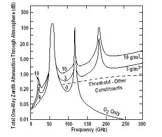
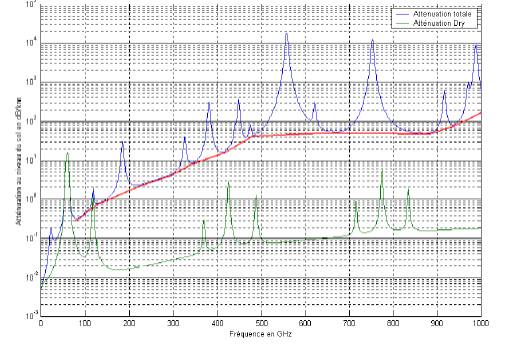
in spite of the atmospheric absorption which is graphed here. I have inserted comments here and there in
the submissions that follow, I hope it doesn’t take away from the innovative
ideas being presented here.
The following helpful and informative ideas were
received within just a couple of days from the group (not in any particular order). There’s a huge head of steam
here. This field is going to break wide
open, fast, given all the talent that’s being harnessed here. There’s lots of lovely spectrum to play with
in spite of the atmospheric absorption which is graphed here. I have inserted comments here and there in
the submissions that follow, I hope it doesn’t take away from the innovative
ideas being presented here.
For terrestrial
communications, the absorption by the atmosphere is of over-riding importance
at these frequencies.
|||||||||||||
Jeff Kruth, WA3ZKR, pointed
out that there’s essentially no stuff on the surplus market. So, I should figure on building my own
multipliers and quasi-optical mixers.
He figures it shouldn’t take more than $25-50 K to get something crude
on frequency.
[NS notes that $25-50k is
out of the price range. But see what
Brian Justin and Luis Cupido have done with a lot less. Then there’s JC Bose who demonstrated 60 GHz
experiments at London’s Royal Institution in 1897 (not a typo-that’s 1897). BTW
note that the Royal Institution is not at all the same as the Royal
Society. Back to Jeff Kruth.]
A friend of Jeff’s built a
300 GHz and a 600 GHz radiometer system in the early '60's for Uncle Sam. To get to 600 GHz with an LO, he said he
just took a 300 GHz Carcinotron signal and doubled it". The LO life was rated for 20 hours and cost
$15,000, waaay back when they had a running time meter on it and when they made
a tune up, he got every thing ready then flipped on the B+ and quickly made a
test, then shut the tube off! The
carcinotron (O type BWO?? or M type, Jeff forgets!) was made by CSF in
France. [NS’ note: I found a reference
to a Thompson Carcinotron at one of the microwave EPR spectrometer web pages].
Jeff notes that the IEEE
archives may include the tale of "Victorian MMW" where Dr. Chandra Bose
demonstrated MMW signals at 60 & 100 GHz before the turn of the 20th
century to the Royal Institution in London.
He did it by spark-excited resonators, and got so much power that his
parallel plate transmission line was glowing (plasma discharge) and the
standing waves could be seen in the darkened room.
Another suggestion was to
try heterodyning long wave near IR lasers in a non-linear medium, use
radiometry methods for detection and send CW.
Jeff repeats: Aint gonna be cheap! On test gear Jeff notes that Brian Justin
worked with an outfit that loaned him enough stuff to do it.
|||||||||||||||||||||||||BACK TO THE TOP
Luis Cupido, CT1DMK,
referred to his article presented at the MWU2001 describing corner cube mixers
and etc .... That stuff gets you beyond
400GHz. A lot of patience is
needed to get it all working. A good
mechanics workshop is more useful than test equipment.
For test equipment Luis recommends
using traditional generators (up to 18GHz or 26GHz) and spectrum analyzers that
allow external mixers. The rest is DIY
because there isn’t much stuff available.
Luis has had good results at 411GHz.
The only decent way to begin
is that you start building yourself a harmonic mixer and a multiplier. We don't need any degree of accuracy for a
start.
Luis’ initial experiments were made with multiplier and harmonic mixer one just
after the other. He could see about
80dB of attenuation. With +15dBm at
34.250GHz this was multiplied times 12 to give 411GHz and then a harmonic
mixer down a few MHz that he could see on the analyzer at -65dBm.
The LO for the harmonic mixer was at 34.251GHz so the 12MHz signal could only
be the 12th harmonic conversion. Luis
is about to write a small article about these experiments.
(the mixers were published at the MWU2001).
Luis did all this on a very small budget and Jeff Kruth, WA3ZKR helped with the
first experiments. The MWU proceedings
show a photo of his first experiments... the big brick in the picture (is
bigger than an ordinary mw-brick) it is a VARIAN 34GHz multiplied source (not a
PLO) he got from Jeff at E-bay for $50.
Luis has a 10m QSO... not much of a record... but 100% ham stuff. He is moving the LO up to 65GHz for better
performance on the multiplication and harmonic mixer.
|||||||||||||||||||||||||||
John Miles, KE5FX, described
the use of Tek 49x analyzers ($3K-$5K) cover up to 325 GHz with external
mixers, but “the upper-end mixers are rare as hens' teeth.” Count on spending another $1K-$2K just for
the 220-325 GHz mixer...
John notes that the
radio-astronomy guys are generating these sorts of frequencies through photonic
mixing techniques. See
http://www.alma.nrao.edu/memos/html-memos/abstracts/abs440.html
for a good .PDF on
this. Just aim two lasers tuned 300 GHz
apart at a photonic crystal, for a 300 GHz IF.
There might be room to do
this on the cheap with diode lasers and homegrown crystals. John recommends
surfing the ALMA (Atacama Large Millimeter Array) site at http://alma.nrao.edu NRAO’s Darrel Emerson
reports some information at http://www.tuc.nrao.edu/~demerson/
. Emerson’s remarkable report on JC
Bose’s researches is required reading, it is at:
http://www.tuc.nrao.edu/~demerson/bose/bose.html
He also suggested
researching the IEEE archives to find the tale of "Victorian MMW"
where Dr. Chandra Bose demonstrated MMW signals at 60 & 100 GHz before the
turn of the 20th century to the Royal Institution in London. Bose did it by spark-excited resonators, and
got so much power that his parallel plate transmission line was glowing (plasma
discharge) and the standing waves could be seen in the darkened room.
John Miles, KE5FX, also
wrote about a Carcinotron which is a powerful BWO for 100-1000 GHz.
||||||||||||||||||||||||BACK TO THE TOP
John, W3HMS, noted that
Bill, W3IY, has a new Millimeter Handbook from France that might have useful
ideas - some of them in English.
||||||||||||||||||||||||
Bill, W3IY, writes - I'm
certainly interested, but I think it's kinda an extreme step. Why aren't you interested in the other
bands, where real QSOs are possible? The trouble with the 300GHz stuff is
that it's hard to work anyone beyond the range of your voice.
I think you will have to be very lucky and come across some surplus equipment,
and even then it will be difficult. WA1ZMS may be willing to help.
I think he gets help from UVA.
|||||||||||||||||||||||
Brian Justin, WA1ZMS/4 –
wrote:
Since I'm one of only two
hams, the other being DB6NT, that have claimed to have had a QSO on the
300+GHz "band" I feel I
should at least tell you my thoughts.
My work was done on 322GHz. That frequency was chosen because it was the
4th harmonic of an 80.6GHz Gunn source that was driving a diode multiplier to
get me on 241GHz. I am able to get
about 750 microwatts of power on 241GHz and much less than that at 322GHz.
Since the multiplier is an anti-parallel diode pair, the even order harmonics
are suppressed. A properly design multiplier for 322GHz should be able to give
you at least a few mW of power provided that you can drive the device with
enough power.
As I understand it, the
DB6NT approach to the question at hand, is to drive a single ended diode
multiplier with a signal in the 30 to 40GHz range and live with the resulting
comb output. Pick off the desired harmonic and you have a rig for the sub
millimeter wave bands.
Industry standard waveguide
goes as high as 325GHz with WR-3 and can be bought from Custom Microwave in
Boulder, CO. The cost however is over $10 per inch. I know. I bought some.
Higher than that and your on your own. Several sub-millimeter wave companies
have their own "standards" for higher frequencies. The folks at the NRAO are a good example.
The mixer/multipliers I own
for 241GHz and up are units that I helped modify-test-manufacture with the
generous help of the guys at Virginia Diodes Inc. They are a spin-off off the
Univ. of Virginia who also has helped me along. These guys are into mm-wave
R&D and have a great semiconductor fab on campus just to make GaAs
diodes. I do work for them, and in
trade the have let me get a few of the "scraps". The commercial costs for such mixers are in
the several K-dollars each. The 80GHz
Gunn sources were semi-homebrew. I
found some 40GHz Gunn diodes listed for sale from a scrap dealer in the UK.
(RSGB news letter) Placed the diodes in a 2Fo mode Gunn cavity I bought from
Harmonix Corp. and have a couple of nice 40mW Gunns on 80GHz.
It all took me over a year
of solid work to get it all together. Home brew 6" dishes, phase locked Gunn sources, converting a 240GHz
multiplier into a mixer, etc...
If I can do it, anybody else
can. But I started out on 47GHz and have worked my way up. I'm sure that Will,
W0EOM can tell you the same thing. You need to start out with lower freq higher
power sources and multiply from there. Direct power on these bands can be done,
but is more of a "lab thing" rather then taking it all roving with
you to a snow covered mountain top.
But do look at the
atmospheric losses on these bands first. I think you'll find that in order to
do >1km you'll need several mW or relatively large dishes to get the job
done. Losses can be several dB per km
on these bands.
If I can answer any questions,
just ask away. Also see: www.mgef.org
for more info on the gear I built.
|||||||||||||||||||||||||||||||BACK TO THE TOP
Will Jensby, W0EOM writes
from Santa Clara, CA:
Neil
and the group - this is a subject near and dear to my heart, as many
know. I am glad that Brian went first, as I have been following him on
this project.
My goal is to get to 241 GHz and be the second one to make a contact on that
band. Since I have contacts on 76, 120 , and 144 GHz, and a drawer full
of millimeter stuff, I hope to do it some day - over 300 GHz will come later.
Bob and I did make 25 km on 144 GHz about two weeks ago, with the best surplus
Hughes mixers and multipliers we have been able to find, searching for over two
years. Which in my mind, makes Brian's effort even more outstanding at 79
km.
I have built one of DB6NT's 241 mixers, but not sure I have a multiplier good
enough to test it. I have seen a signal from a 215 GHz Impatt osc so am
close.
Don't give up the effort to get to 300 GHz, but its not easy or cheap. I
would likely pay over $500 for a mixer that works on 241, ones I have found so
far are over $2500.
|||||||||||||||||||||||||||||||||
Gary Lauterbach, AD6FP, has
been working toward 240/300 GHz capability
and has collected the parts. The
critical part was getting diodes capable of sub-mm operation. The group at NMRC sold him 5 honeycomb
diodes (X81) at $100 apiece. The diodes
can be used in open structure mixers through 2.5 THz. He also has 5 varactors
that should be capable of several mw at 300 GHz.
A good reference on mm and
sub-mm mixers is the mixer book by S. Maas, also check out his web site: http://www.nonlintec.com/. Maas is one of the well known experts in this
field.
|||||||||||||||||||||||||||||||||||||||
Jon, W2MXW, has decided on a
homebrew approach including make/machine your own
mixer blocks, corner cubes,
etc. and use scrounged parts. Some kind souls on this reflector have provided
materiel for the cause as well. You can also get stuff machined to your specs
and reasonably priced from (note: I have no affiliation therewith)
www.emachineshop.com Forget the
rare/big bux commercial stuff, you can do it (relatively) cheaply, with
ingenuity. For LO/RF sources, try to get a surplus Gunn osc. at as high a freq.
as you can find and injection lock it, or, use a brick and multiplier (for
example one of my experimental setups is:
12.5 GHz brick->tripler
[~37.5 GHz]->corner cube harmonic mixer (8th harm. on up is 300 GHz-up).
If you can get one of those
surplus 20-someodd or 38 GHz units to use for your osc. or if you already have
capability to provide a stable sig on 24 GHz or higher you're ahead of the
game.
I'm also working on getting
on 1000 GHz (1 THz) -plus. Investigating BWOs,
mixing lasers too (on a semi-related note, also working on stabilizing
laser diodes for heterodyne mixing for work at optical freq., another 'passion'
of mine :-) SHF Micro sells low-cost Schottky mixer diodes which when removed from
their ceramic pills can be used in the corner cubes with a catwhisker, or as-is
in lower-freq. mult. or mixer stages. There is a (relatively) low cost
commercial source for the 'honeycomb' diodes too. Tiny, delicate things so
invest in a dissecting 'scope so you can see what you're doing. MIM
(metal-insulator-metal) diodes can also be homemade, but are rather unstable
(like galena detectors in xtal sets!) Some of the Schottkys and MIM diodes can
operate up to optical freqs!! In all cases (except maybe spark, hihi) power
will be very low, but still useful. You will be in the QRPpppp region with
microwatts or at best a couple mW. Don't hope for watts or even dozens or 100's
of mW. Fortunately antenna gain will help take care of that and is very easy to
come by this high up. Greatest limitations on range are probably poor NFs and
atmospheric loss. Humidity is your enemy so QSOs are best attempted when dry.
*grin* Have played with spark too (above 300 GHz not [yet] allocated so FCC
prohibition of Class B emission doesn't apply). Easy to use waveguide,
perforated metal screens (yes, filters that actually work as EM
"filters"!), and various other materials to ensure you really are on
the desired bands.
Mercury vapor and some metal
halide lamps also provide broadband energy in this region, useful as noise
sources and for molecular spectroscopy, if that's your cup of tea! Crude detectors are made of homemade
point-contact silicon or MIM diode in a parabolic reflector. A form of the
latter is what J. C. Bose used (the "iron point contact detector").
Fascinating stuff. The main problem from my perspective is that AFAIK there
isn't anyone near me interested in this stuff so I have to make TWO of
everything if I expect to have a QSO! I'm working on a site compiling all the
mmw/far IR info I've collected on the subject over the years (quite a bit of
it, too!), but it'll be awhile yet before it can go online (time constraints,
you know the drill).
||||||||||||||||||||||BACK TO THE TOP
Bob Wesslund, WØAUS, is
working his way up in frequency. He has
equipment up to 24 GHz for use on an
antenna range. He uses an avalanche
diode to generate 10 GHz signals. The
avalanche diode has the advantage that it can be amplitude modulated with 1000
cps for a range. For 24 GHz he uses an Avalanche diode that is am
modulated. Both of the units came as
surplus for motion detectors for missile silos. For 47 GHz he has a 23.5 GHz Gunn diode and is looking for a pin
diode modulator and a doubler for 47 GHz.
|||||||||||||||||||||||||
Web pages of interest:
IEEE MICROWAVE AND GUIDED
WAVE LETTERS, VOL. 4, NO. 2, FEBRUARY 1994 37
“A 335
GHz Quasi-Optical Schottky Receiver” by Walid Y. Ali-Ahmad, Memberj IEEE, and Gabriel M. Rebeiz, Senior Member, IEEE
http://www.eecs.umich.edu/rebeiz/Completed%20Research%20Papers/335_GHz_QO_Rec94.pdf
||||||||||||||||||||||||||
Nuclear Instruments and Methods
in Physics Research A 436 (1999) 430}442
A new frozen-spin target for
4p particle detection
Ch. Bradtke, et al
http://wwwa2.kph.uni-mainz.de/gdh/publications/pdf-files/bradtke.pdf
In the GDH-experiment a
carcinotron (Thompson CSF) was used as microwave source. It
provides a power output of
3.5W and its central frequency of 70 GHz corresponds to the electron Larmor
frequency at a magnetic field of 2.5 T.
|||||||||||||| BACK TO THE TOP |||||||||||||| |||||||||||||||| |||||||||||||||||| |||||||||||||||| |||||||||||||
AND NOW THE ALTERNATE IDEAS
Steve VE3SMA
Alternate approaches
(inspired by 300 GHz+ thread)
SPARK IDEAS
Here in Canada we have no
mode or bandwidth restrictions in the microwave & mm-wave bands (as long as
you stay in the band) so I also gave some thought to spark as a cheap way to
get some power on the mm-wave bands (we don't have bands over 300 GHz here
though special permission could probably be obtained). It got me reading some
VERY old textbooks !
There seems to be a problem
of efficiency, however. Since the
oscillation dies out after a number of RF cycles (about equal to the Q of the
cavity) you need to keep repeating the spark to keep power coming out. However, if you do this at an audio rate as
was done in the early days of radio, a millimetre-wave spark transmitter has
zero output nearly all the time
(because of the large ratio
of carrier to modulation frequency).
Furthermore, I would expect the peak power to be limited by the small
size of the cavity, so it might be hard to get much average output. Perhaps microwatts, like WA1ZMS, but the
signal bandwidth is so wide it would likely get lost in the noise. I haven't really given a lot of thought to
the use of a much higher modulation (spark repetion) frequency, say tens of
MHz, but that might offer some chance if the arc could be extinguished fast
enough.
It seems to me that there must
be some room for amateurs to use techniques which are not suitable for
commercial use to avoid the cost of diodes and other mm-wave devices. We are prepared to sit and tweak constantly
(some of us prefer to, I think)which is totally impractical for most
"real" applications.
One idea that got me
thinking was running across some papers which showed experimental results of
using ordinary garden-variety neon bulbs as X-band detectors...they actually
worked quite well, but there was no info regarding other frequencies. They would go well with a spark
transmitter...no diodes, transistors, nothing solid-state at all ! I was once told that there was such a thing
as a ferrite multiplier...maybe we could learn how to make one using bits of
ferrite from surplus isolators - no diodes needed ?
||||||||||||||||||||||||||||||||||||||||
Jon W2MXW replied:
A quick Google search turned
up these references for use of a glow lamp as mmwave detector:
http://www.csonline.net/bpaddock/scalar/default.htm
see file "Neon lamp
based scalar detector" mentions use of specially-constructed glow lamps as
plasma diodes up to 100 GHz. Also has circuits for making your own glow lamp
detectors. Well, off to the basement to have some fun!! :-)
Also, from same page
"references" section:
N.S. Kopeika and N.H.
Farhat, "Video Detection of Millimeter Waves with Glow Discharge
Tubes," IEEE Transactions on Electron Devices, Vol ED-22, pp.
534-548, August, 1975.
N.S. Kopeika, B. Galore, D.
Stempler, and Y. Heimenrath, "Commercial Glow Discharge Tubes as Detectors
of X-Band Radiation", IEEE transactions on Microwave Theory and
Technology, Vol MTT-23 pp. 834-846, October, 1975.
N.S. Kopeika,
"Millimeter-Wave Holography Recording with Glow Discharge Detectors,"
Int. J. Electronics, Vol 38, pp. 609-613, May, 1975.
Also mentions sensitivity of
10 GHz (X- band) neon bulb detectors, ranging from 40 uV (best case) to 137 uV
(worst case). Common NE-2U (should that be "-H"?) rated at 77 uV.
|||||||||||||||||||||||||||||||||||||||||||
Jerry, K0CQ, writes:
I remember discussions on
the R390 page in past years about the radioactivity tags on military versions
of 0A2. Seems they need a bit of light to trigger reliably, and tube type
military radar in pressurized enclosures for high altitude aircraft don't
supply any light to the 0A2, so the 0A2W has a bit of radium or similar to
provide a trigger.
Maybe some of the variation
in neon sensitivity (besides individual variation on neon pressure) could have
come from radioactive particles in phosphor coatings. Those might vary from
production run to production run depending on the cleanliness of the phosphor
chemicals.
Perhaps the neon RF detector
could use a bit of tritium adjacent to the envelope to increase its
sensitivity. I presume they do a DC bias. Maybe an AC bias, ala super
regeneration could be used. Maybe some sort of modulated light bias... And
since I've NOT read the references, I may have just reinvented all their
techniques.
Do they still use a bit of
something radioactive in some smoke detectors? How about antistatic brushes (as
we used to use on vinyl records?) Or is anything weakly radioactive a sure
death to sales so it can't be bought any more? How about a WW2 surplus watch
face with glow in the dark numbers? There's a bit of radioactivity in the
chemicals in some gas lantern mantles.
Entire content of prior 4 paragraphs is copyright of Dr.
Gerald N. Johnson, electrical engineer.
Reproduced by permission with thanks.
|||||||||||||||||||||||||||||BACK TO THE TOP
Zack Widup, W9SZ, notes as
follows:
Bob Paddock is an old friend
of mine. He's not a licensed ham but
knows a lot about RF. He gets into the
"weird science" aspects quite a bit.
A few years ago I did a few
experiments for him with a circuit he designed using coils wound on special
ferrite materials to utilize the Barkhausen effect to detect (in theory) scalar
waves. It was quite fascinating. These
were done at VLF frequencies.
Now I'm going to have to
play around with neon bulbs/tubes as mm wave detectors!
||||||||||||||||||||||||||||||
Geoff Blake G8GNZ , commenting on Gerry Johnson’s note,
writes as follows:
IIRC the ionisation source
in the 0A2W was tritium, as was used in all versions of the 0G3/85A2 which was
used in virtually all Tektronix 5XX series oscilloscopes. We used dozens of
these (85A2's) where I then worked and we stored them unwrapped for space
reasons. When our Radiological Protection Officer (my boss) discovered this, he
had a fit with his leg up!
We then carried out an
investigation and discovered that we would have to break some 2,000 of 85A2's
and collect ALL the tritium trioxide (?) powder before we had even a minimal
risk!
Of course, we developed a
healthy respect for things that glow in the dark, even if they require the
application of a 100Vdc or so before they do so.
I for one thought K2RIW's
article excellent!
|||||||||||||||||||||||||||||||||| BACK TO
THE TOP
From:
"wa1zms@arrl.net" <wa1zms@worldnet.att.net>
To: W1MBA reflector and
others
Sent: Tuesday, March 04,
2003 7:21 PM Subject: [Mw] 322GHz DX...
We (W4WWQ and myself),
pushed our 322GHz "DX" to 1.4km on March 4th, 2003.
QSO Details:
Date: 3/4/03
Time: 01:17z
W4WWQ 37-21-14.7
79-10-13.7 FM07ji
WA1ZMS 37-21-23.6
79-11-10.8 FM07ji
Distance: 1.432km
Freq: 322.6GHz
Mode: FSK-CW
Temp: 0C
Dew Pt: -6.7C
RH: 61%
Pressure: 992mb
Atmos Loss: 10.6 dB/km
<---WOW!
We likely would have had
better results if we had a day with a lower dew point. The QSO on the WA1ZMS end
was tough at best. Problems
with frequency stability limited the application of weak signal software like
Spectran, etc.. So good old fashion 5WPM CW and headphones were used. Since one
station has a better RX mixer than the other (isn't that always the case!)
Pete, W4WWQ had about 6dB of margin on his end while I had 0dB on mine.
The gear is the same that
was used in the recent past for other 241/322 GHz QSOs. Photos of gear can still be found at
www.mgef.org For this QSO the 80GHz drive level into the diode multiplier was
reduced during RX to get a lower conversion loss.
I hope that others can get
some gear running on +300GHz and give this DX record a smashing!
73, Brian, WA1ZMS/4
||||||||||||||||||||||||| BACK TO THE TOP
Thanks to all the authors
for their contributions. Some of the
above notes are copyright to the authors and their permission should be sought
before reprinting their contributions.