This technology has been applied in a wide variety of disciplines including economics, the social sciences, environmental studies, and politics. Some elements of the technology to be covered here include causal loops and stocks and flows.
Causal Loops
Causal Loops are simple diagrams that are drawn to indicate hypothesized relationships among the system elements under examination. Their use is a first step in creating a working model of an environment. As an example the causal loop diagram below depicts an organizational situation where an increase in layoffs result in a decrease in morale. This decrease then causes a reduction in productivity. This effect then feeds back to produce increased layoffs. Right away then we see that the concept of feedback is central to this technology.

The O in this loop indicates an Opposite effect in the relationship, i.e. a decrease in productivity causes an increase in layoffs. An S in the loop indicates effects in the Same direction. That is a decrease in morale causes a decrease in productivity. This particular loop is an example of a reinforcing loop. Causal loops may be interpreted as negatively or positively reinforcing. In the instance just described it would be classified as a negative reinforcing loop. A positive reinforcing loop would be indicated by a decrease in layoffs which would then produce an increase in morale which further produces an increase in productivity. In the causal loop nomenclature a large R is placed inside the loop to indicate its reinforcing nature. The two vertical bars (||)between Morale and Productivity indicate a delay. As indicated in this diagram, a decrease in morale may not decrease productivity immediately, but over time will cause a reduction.
While causal loops are an effective method for describing generalized relationships, a need for finer granularity in the description is often necessary. In reviewing the example above many questions arise. For example:
How many layoffs are necessary to produce a reduction in morale?Another ancilliary method, commonly called Stocks and Flows, builds upon causal relationship diagrams and provides a mechanism for in-depth, time based observation of the system.
How much is morale reduced?
How do we measure the reduction?
How much time will pass before moral reduces productivity?
Stocks and Flows
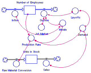
Stocks and flows allow a finer granularity in the analysis of the model relationships and also are the basis for running system dynamics simulations. No straightforward method for converting causal loop diagrams into stock and flow diagrams has been formulated . However experts in the field have formulated heuristics for aiding participants when building models. The stock and flow diagram below is one expanded interpretation of the simple causal loop above

In the above example the number of employees in the organization, indicated by the box, may decrease through an outflow, indicated by the valve, triggered by the influence of a demand in the job market, as indicated by the circle, line, and arrow. Or the units in stock may be increased by additional raw material conversion caused by an increase in the production rate which was increased by a boost in morale, which was influenced by increased hiring.
Note that the symbols utilized are different than those in causal loops. The box indicates a stock, where elements accumulate, and then increase and decrease over time. The circle with a small T on the top represents a flow control, similar to a valve. And the circles with extending lines and arrows indicate influences. Finally the clouds indicate indeterminate supply.

The stock and flow symbols used in system dynamics are derived from the early work of Professor Jay Forrester of the Massachusetts Institute of Technology. He is considered the father of system dynamics.
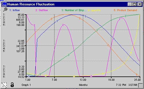
Output in stock and flow systems is typically depicted in the form of time graphs such as that shown below. The X axis indicates time and the Y axis contains scaled values of the variables under observation.

These diagrams enable model builders to see relationships which could not be seen using conventional analysis and tools such as spreadsheets. This is true both because of the complexity of variable interaction, and because of time influences. In the above diagram such things may be seen as hiring delay consequences, effects of seasonality, the push and pull of external job market attractions, and the long term result of crisis reactions such as massive layoffs.
(c) 1998 John H. Saunders. Permission granted for unrestricted use in academic environments.